在阅读本文之前,你也许应该看看 EVMeter-理论篇
本文目录
设计蓝图
继上次我们分析了测光表的原理,并do了一点math之后,我们得到了lux与曝光参数之间的直接关联,由此我们可以设计一个测光表,我想让它具有这样的特性:
- 使用高精度平面入射型光传感器,直接输出lux值
- 配备辅助RGB传感器,同时可以得到色温数据(其实就是一个光传感器+拜尔滤色镜)
- 使用0.96英寸128×64的OLED屏幕实现数据可视化,并提供良好的UI互动界面
- 使用3个按键进行人机交互,其中一个切换功能键,另外2个调整数据
- 小型化,电路板大小3x5cm,配备3D打印外壳,可以直接安装到相机的热靴上
- 使用锂电池供电,尽量采用低功耗设计思路,使用600mAh的电池,同时提供micro-usb接口充电
- 具有升级接口(ST-LINK),方便后续调试、升级算法
- 具有掉电保存上次操作设置的功能。使用外接EEPROM实现(因为便宜( ̄▽ ̄)")
并且,这是初代鸡。我还想给他添加更多更酷的特性,比如用旋转编码器(类似单反上的拨轮)来代替3个笨拙的按键,使用镀漆的航空铝型材做外壳,将micro-usb升级成type-c,并且板载ST-LINK,只需一根usb type-c数据线即可轻松升级……等等等等(坑逐渐扩张.jpg)
Hardware Design
硬件选型永远是最纠结的环节。。之一
MCU的选择,考虑到PCB的空间问题,我将LQFP48封装的单片机(STM32F1等)都扔出了选择范围。最终我盯上了TSSOP20的STM32F070F6P6,48Mhz主频,6K RAM,32K Flash,而且足够便宜,只需要3元/pcs。(其实主要是优信能一站买齐hhhhh)
传感器是最关键的部分了。我觉得在这种性能要求高的场合,还是氪金比较好)
于是我选择了TSL2591,具有近乎人眼动态范围的光强传感器,IIC数字接口直接输出Lux,非常方便且精准。就是有点贵,一片就要25RMB+
辅助RGB传感器嘛,就选了个TCS34725,淘宝卖的多,资料也好找。(它不要求对光强有多高的精度,我们只要它的RGB数据)
然后就是其他杂七杂八的小元件选择啦…
最后还是拿开源人都喜欢的KiCad画了板子~
Layout
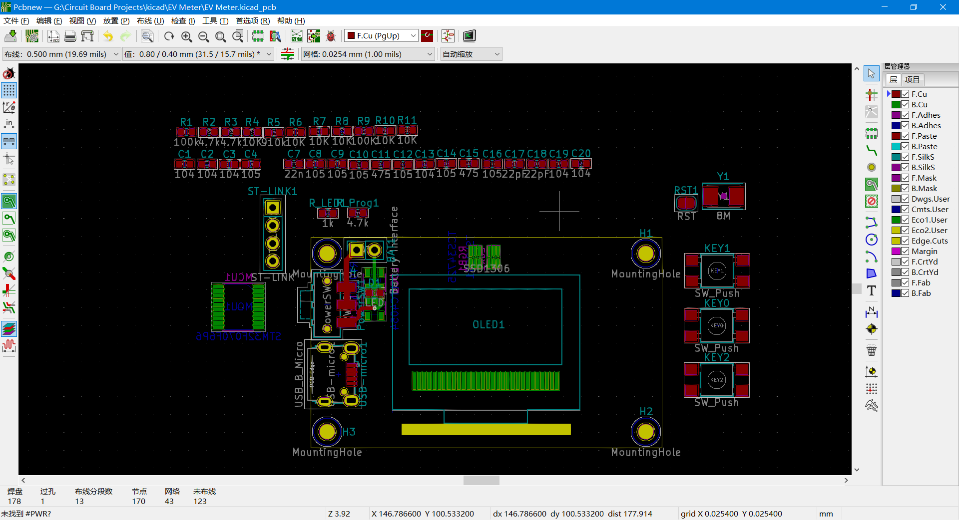
然后想加断电保存功能,就塞了一片24c02上去。
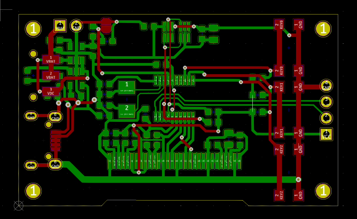
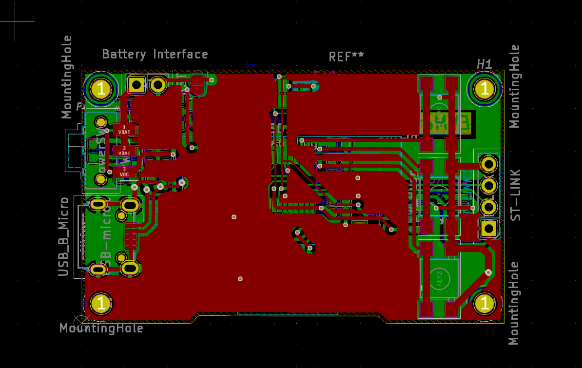
(说着说着开启了光线追踪.jpg)
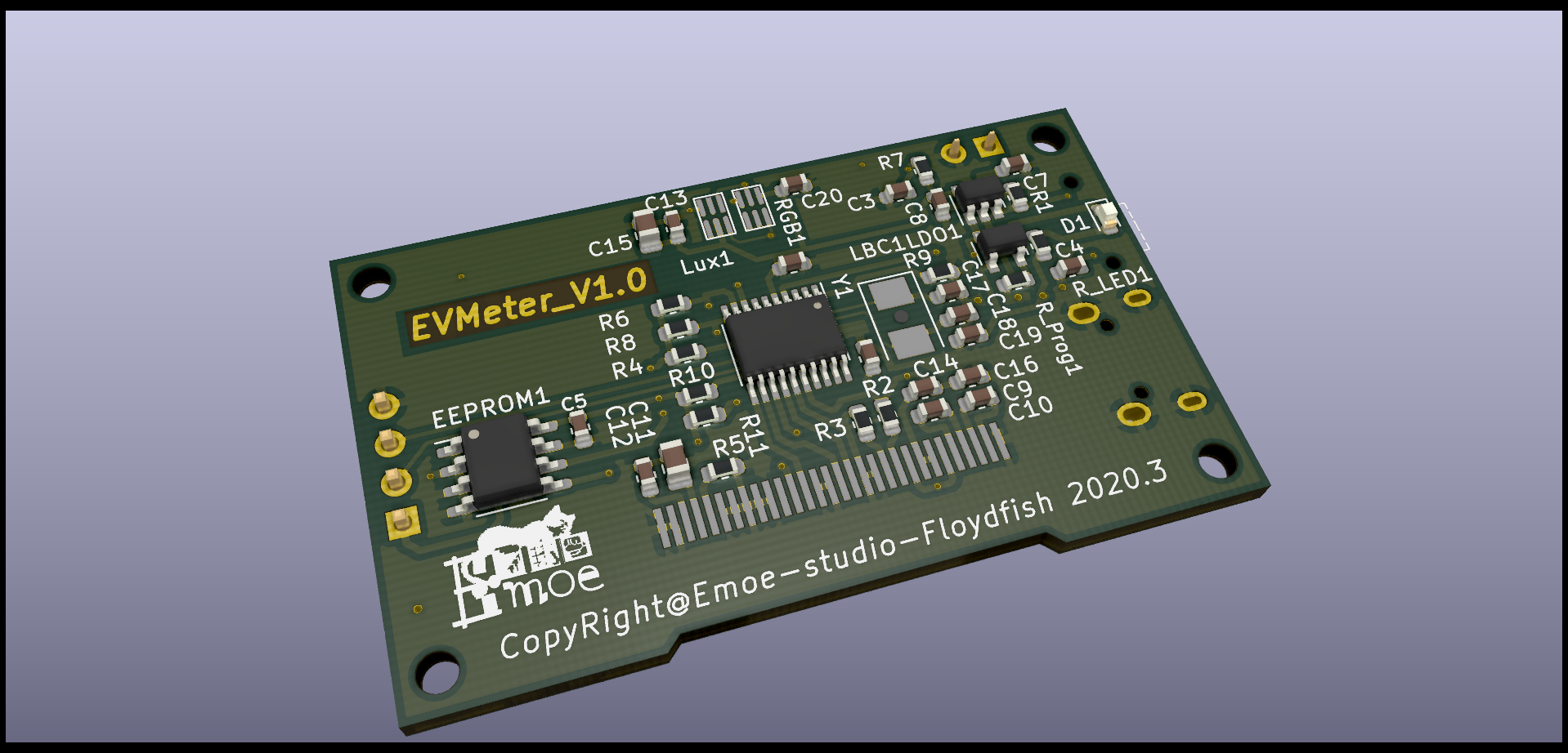
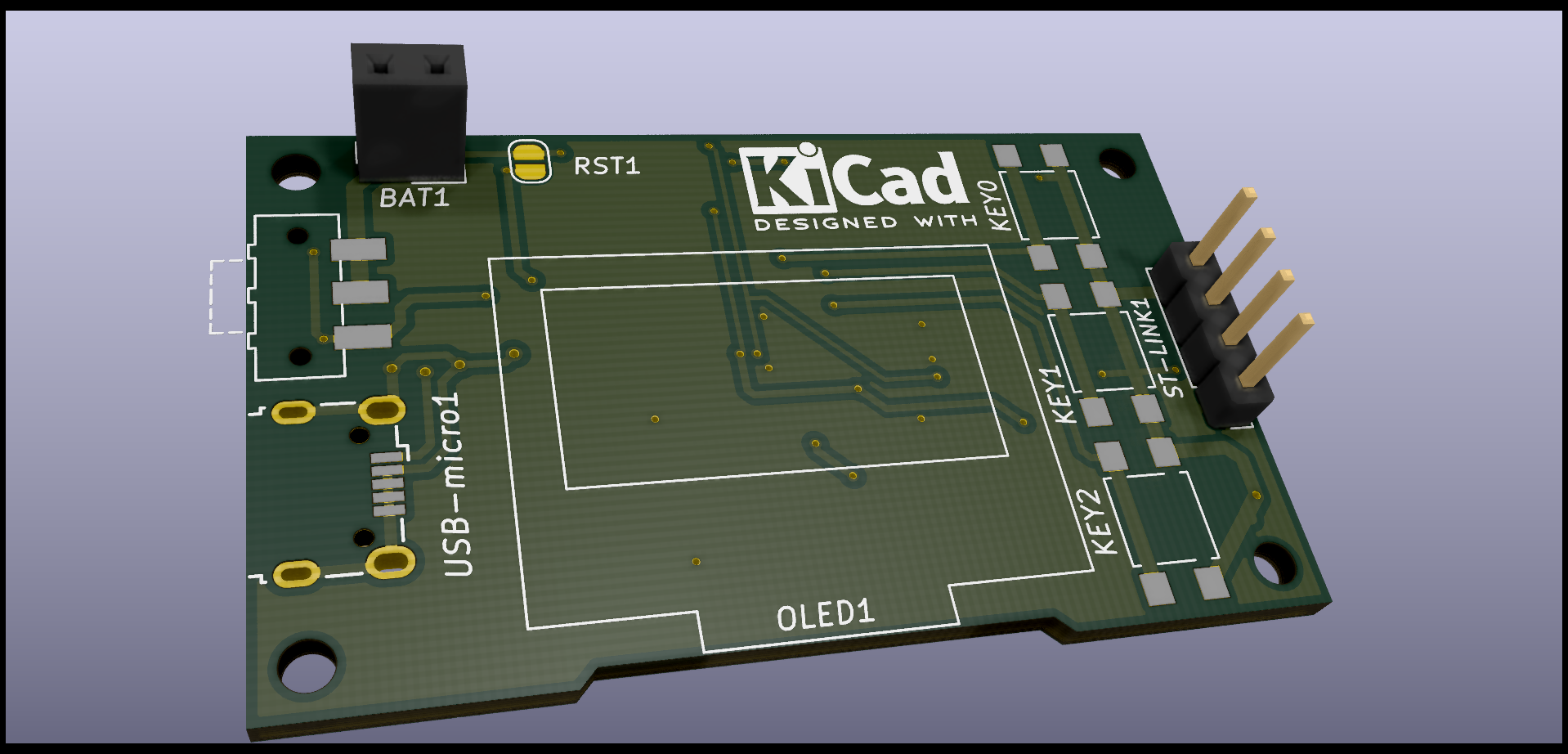
啊♂ 光追就是爽。
接下来就是传感器和mcu的联调啦
但是板子还在我电脑里,还没拿去打样呢。(打样了我在家里也没元件没工具55555),还是等俺回学校了再说吧。。。
2020.4.3日更新
前几天我在网上买的c8t6和一些小模块终于到了….
于是开始了快乐的填坑之路√
就在昨天晚上,我写了一个验证模块来验证算法正确性,给定光圈和ISO,自动根据lux值计算曝光时间,没想到一次就成功了~
别高兴得太早…
但是等我拿出单反一测,似乎偏差不小诶…
于是坑越挖越大…在AMS官网上找到了3篇Application Note,开始啃。。。
色温测量原理(DN25)
翻一翻应用手册,记录几个专业名词:
- CCT(Correlated Color Temperature)-相关色温
- Chromaticity-色度
- Planckian Locus-普朗克轨迹(别问我怎么跟普朗克扯上关系的…其实是AN里讲色温从普朗克黑体辐射开始讲起…)
并且还得到一张"色图"
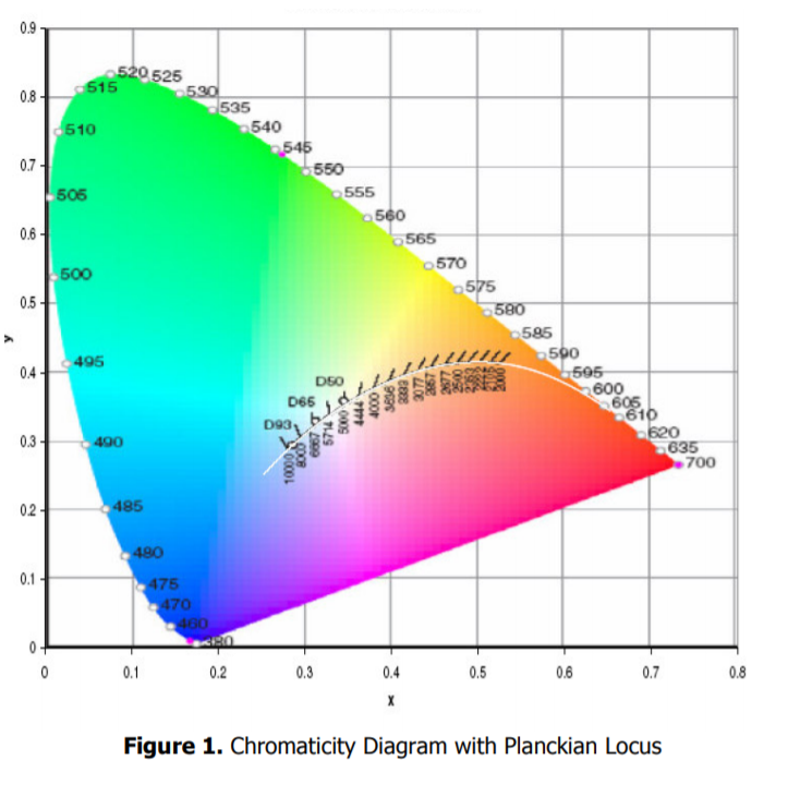
这里以TCS3414CS传感器为例子,AN说明了它的工作原理:
The TCS3414CS digital color sensor returns data from four channels: red(R), green(G), blue(B) and clear(C)(non-filtered). The response from the red, green and blue channels (RGB) can be used to determine a particular source’s CCT. The key to accomplishing this is to transfer the RGB responses to the chromaticity diagram in Figure 1 and find the point on the planckian locus closest to our source’s chromaticity point
大致意思就是把3个通道的强度值传输到上面那张色图里,然后找到普朗克轨迹上最接近光源点的色度点,就能得到色温。
接下来就是算法了…
Chromaticity coordinates (x, y) are based on standard tristimulus values (XYZ). These standards are set by the Commission Internationale de l’Eclairage (CIE). The CIE is the main international organization concerned with color and color measurement.
ohhhhhh,这个标准3刺激值(Google机翻)是国际照明委员会设定的标准(CIE)。
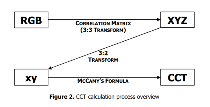
In order to acquire a CCT for a given light source using a TCS3414CS, we must first map the sensor response (RGB) to the CIE tristimulus values (XYZ). It is then necessary to calculate the chromaticity coordinates (x, y) and finally the correlated color temperature (CCT). Figure 2 displays an overview of this process as well as the methods used for each transformation.
整个过程就是这张图:
根据一些niubi的公式,得到伪代码如下:
/* RGB to XYZ transformation */
X = (-0.14282)(R) + (1.54924)(G) + (-0.95641)(B)
Y = (-0.32466)(R) + (1.57837)(G) + (-0.73191)(B) = Illuminance
Z = (-0.68202)(R) + (0.77073)(G) + (0.56332)(B)

/* Calculate Chromaticity coordinates */
x = X/(X+Y+Z)
y = Y/(X+Y+Z)

/* McCamy’s formula */
// provide a maximum absolute error of less than 2 degrees Kelvin
for color temperatures ranging from 2,856 to 6,500 K
CCT = 449*n^3 + 3525*n^2 + 6823.3*n + 5520.33
/* where n = (x − 0.3320) / (0.1858 − y) */
这部分对应TCS34725库中的这一段代码:
/* 1. Map RGB values to their XYZ counterparts.    */
/* Based on 6500K fluorescent, 3000K fluorescent   */
/* and 60W incandescent values for a wide range.   */
/* Note: Y = Illuminance or lux                    */
X = (-0.14282F * r) + (1.54924F * g) + (-0.95641F * b);
Y = (-0.32466F * r) + (1.57837F * g) + (-0.73191F * b);
Z = (-0.68202F * r) + (0.77073F * g) + (0.56332F * b);

/* 2. Calculate the chromaticity co-ordinates      */
xc = (X) / (X + Y + Z);
yc = (Y) / (X + Y + Z);

/* 3. Use McCamy's formula to determine the CCT    */
n = (xc - 0.3320F) / (0.1858F - yc);

/* Calculate the final CCT */
cct = (449.0F * powf(n, 3)) + (3525.0F * powf(n, 2))
        + (6823.3F * n) + 5520.33F;

/* Return the results in degrees Kelvin */
Lux and CCT Calculations(DN40)
emmmm?不是和上面一样吗…别急, DN40 提供了额外的解决方案,它主要回答了如下几个问题:
- What is the maximum lux level that can be measured?
- What is the accuracy of the lux calculations due to the digital nature of the measurements?
- Is the light source too bright resulting in saturation of the device?
- What happenswhen the device is placed behind dark glass?
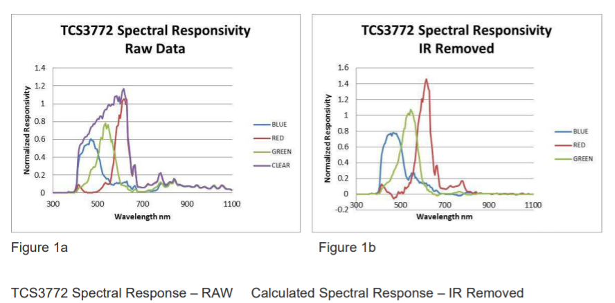
IR Rejection
在某些应用场景,红外成分是微不足道、可忽略的,比如测量一个LED的色温。
但在某些场景,如测量周边光环境,白炽灯,阳光等含有大量红外成分的光源时,传感器上自带的IR Filter显得有些无力。。。
所以我们需要使用改进的算法来补偿IR Filter的不足。
在传感器上,如TCS34725-一个拥有12个光电二极管阵列的传感器,其中分成4组,分别附有Red、Green、Blue滤镜和无滤镜(Clear),可见这种传感器本身是没有IR通道输出的,所以我们需要根据RGBC的值间接计算IR。
一个简单的算法如下:
// Calc IR content
IR = (R + G + B - C) / 2

// Remove IR from source
R' = R - IR
G' = G - IR
B' = B - IR
C' = C = IR
IR滤除前/后对比
Lux Calculations
再来创建一个G2方程:
(说到G2,就不得不提……)
G2 = R_Coef * R' + G_Coef * G' + B_Coef * B'在这个方程里,G’通道的系数常为1,这样才能让CPL(Counts per Lux)来控制整体系统的增益…
G2是通过一个系数方程直接与Lux相关的,这个方程有如下几个参数:
- GA(Glass Attenuation)
- DF(Device Factor)
- 结合上面2个,得到DGF(Device and Glass Factor)
可以简单的把它们理解为在不同应用场景下的校正系数,CPL计算如下:
CPL = (ATIME_ms * AGAINx) / (GA * DF)
alse means: CPL = (ATIME_ms * AGAINx) / DGF

Lux = G2 / CPL
具体的GA、DF如何取值,DN40里有详细的介绍。
ColorTemperature Calculations
IR成分的滤除对色温计算至关重要。用上面提到的IR Filter算法,得到R’和B’,再用如下的公式来计算ColorTemp:
CT = CT_Coef * B' / R' + CT_Offset对应代码是这样的:
    /* AMS RGB sensors have no IR channel, so the IR content must be */
    /* calculated indirectly. */
    ir = (r + g + b > c) ? (r + g + b - c) / 2 : 0;

    /* Remove the IR component from the raw RGB values */
    r2 = r - ir;
    b2 = b - ir;

    if (r2 == 0) {
        return 0;
    }

    /* A simple method of measuring color temp is to use the ratio of blue */
    /* to red light, taking IR cancellation into account. */
    uint16_t cct = (3810 * (uint32_t)b2) / /** Color temp coefficient. */
                   (uint32_t)r2 +
                   1391; /** Color temp offset. */
Device Count Saturation
当光线逐渐变强,Clear通道一般会率先饱和(R+G+B 接近C),如果Clear通道饱和,那么我们上面提到的IR Rejection算法就失效了…
在这时我们要么不用,要么用更复杂的算法去Reject IR content。
Analog Saturation的满量程值取决于我们设定的传感器曝光时间,多数设备累积1024 counts per 2.4ms,最大counts是65535 counts(16bit),达到满量程需要154ms,所以在配置曝光时间154ms以上时才能达到16bit的满量程。
如果ALS的积分时间大于154ms,那么Digital Saturation就会在Analog Saturation之前出现,也就是count到了65535,具体在代码中体现如下:
if ((256 - TCS34725_IntergrationTime) > 63) {
    /* Track digital saturation */
    sat = 65535;
} else {
    /* Track analog saturation */
    sat = 1024 * (256 - TCS34725_IntergrationTime);
}
Ripple Rejection & Saturation
50/60HZ纹波对我们的光积分过程也有很大的影响。当传感器的积分时间很短时,我们需要注意滤除这些工频光源干扰,代码如下:
/* Ripple rejection:
 *
 * (a) An integration time of 50ms or multiples of 50ms are required to
 *     reject both 50Hz and 60Hz ripple.
 * (b) If an integration time faster than 50ms is required, you may need
 *     to average a number of samples over a 50ms period to reject ripple
 *     from fluorescent and incandescent light sources.
 *
 * Ripple saturation notes:
 *
 * (a) If there is ripple in the received signal, the value read from C
 *     will be less than the max, but still have some effects of being
 *     saturated. This means that you can be below the 'sat' value, but
 *     still be saturating. At integration times >150ms this can be
 *     ignored, but <= 150ms you should calculate the 75% saturation
 *     level to avoid this problem.
 */
if ((256 - TCS34725_IntergrationTime) <= 63) {
    /* Adjust sat to 75% to avoid analog saturation if atime < 153.6ms */
    sat -= sat / 4;
}
暂时摸鱼d=====( ̄▽ ̄*)b
5.20日更新
哈!别看今天是520,俺还是很勤奋地在更新的!!
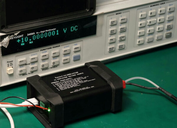
俺画的板子老早就打样ok并到手了,前几天才花钱买了一批元器件,开始了我们的硬件方案验证~
刚到手的小板几~
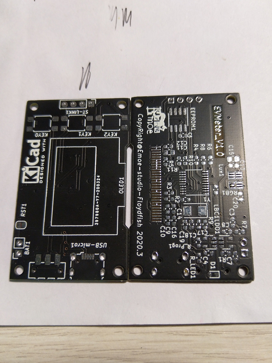
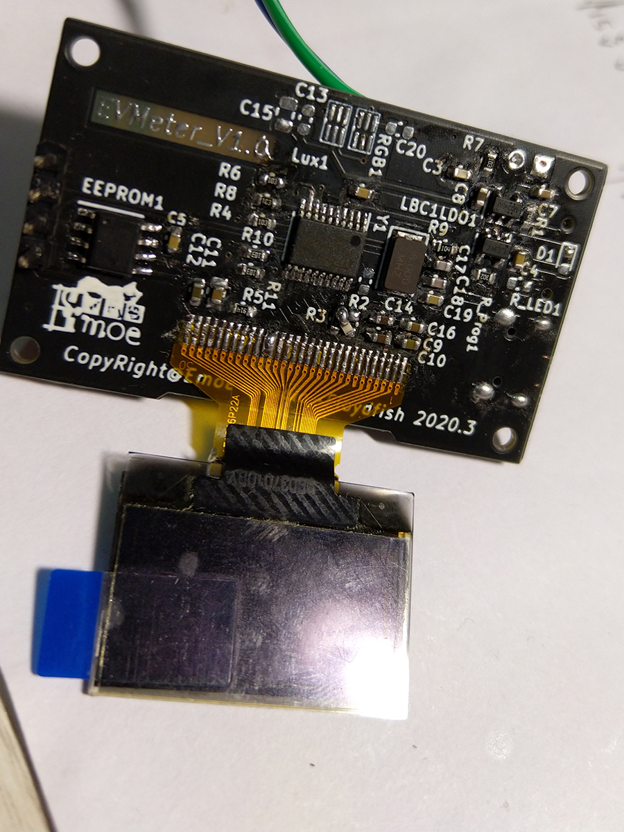
焊接好了的样子~
手头没有洗板水,为了焊板子还买了个T12焊台和小刀头...由于手里的锡比较垃圾,残留助焊剂贼多,所以看着很恶心口区(
Bug report
这一板是直接废掉了orz 因为我焊完了MCU才发现,我的传感器焊盘画错了,应该镜像一下的。。。。。。
这就非常坑爹了.jpg,不过我本来也有换MCU的打算啦,所以这个板子也不算是白打了~它可以帮我验证我的其他硬件方案有没有问题!
Bug#1
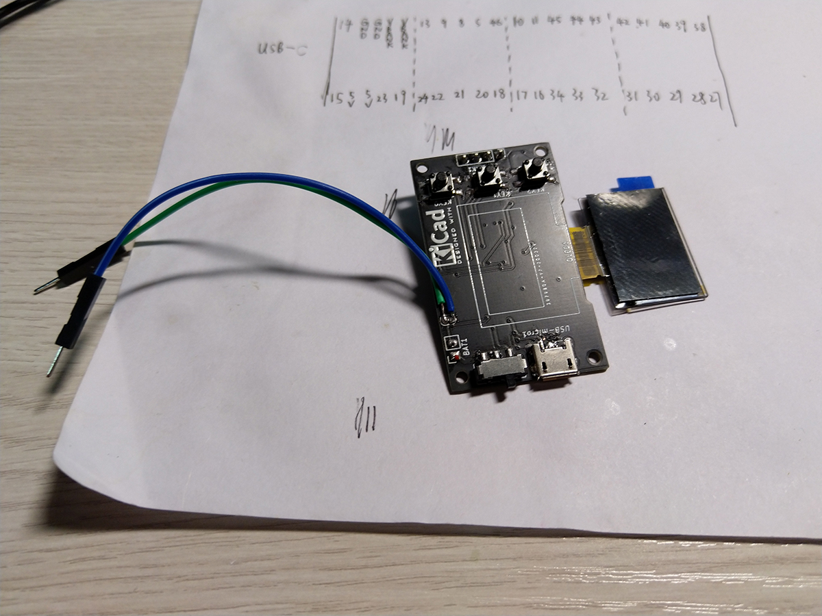
只留了一个调试焊盘作为单片机复位,这是一个错误的选择...具体体现为复位脚上电位不稳定,单片机无法正常连接到ST-Link并被识别...然后我手动焊了2根线上去手动复位(
大家千万别学我啊233 复位还是焊个按键上去比较好,如果软件非常成熟了的话接到Vcc也可以。
Bug#2
我发现SSD1306的驱动电路我画错了。
当时画电路图可能脑抽了,没看清楚datasheet里写的几行字...总之就是一个电阻应该接地,我给接到3v3了,还有一个数据脚D2在串行模式的时候需要和D0连接到一起,我没连...
在用各种骚操作手动修复了这些bug之后,我烧录了SSD1306的测试程序:
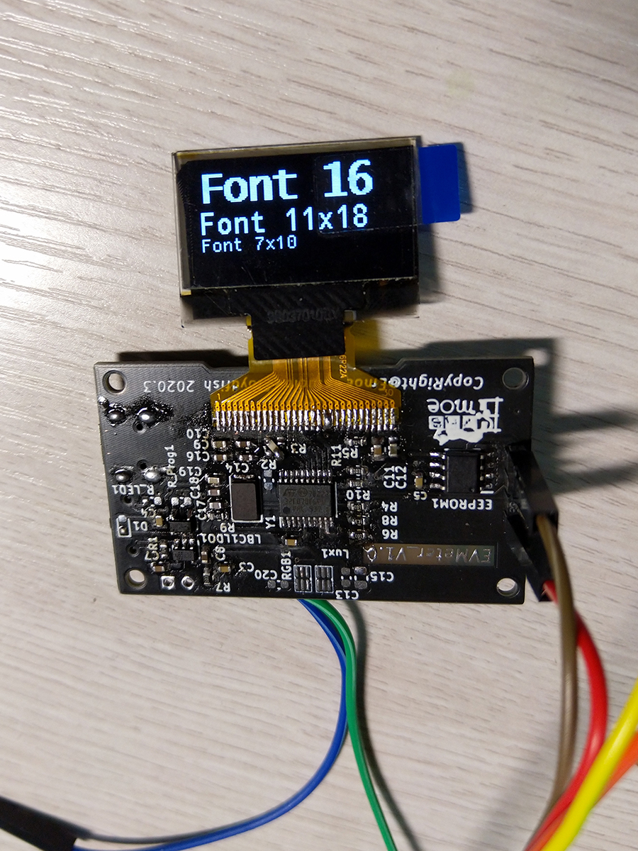
(我已出舱,感觉良好~)
Bug#3
也不算是Bug吧,就是一点小发现。
比如说,LT4054锂电充电ic在不接锂电池的时候是不导通的...(表现为插上了USB供电板子也不会工作 (摊手) ),然后我找了个n年前买的不知好坏的小锂电接上去了,开启开关,正常工作~
后续
应该是要重新打板子了(悲
然后呢,我预计会做如下改动:
- 去掉占地方的大按键,换用贴片中龟按钮
- 不用外部晶振,用单片机内部RC(降低成本,节省PCB空间)
- 更换MCU为STM32F070CBT6(LQFP-48),它有128KB的FLASH和16KB的RAM,可以满足我的代码需求...(F6P6太弟弟了555)
- 改用Type-C插口供电
- 可能采用1.14英寸的IPS屏幕取代OLED(暂定)
![[Bonjour STM32] No.4-demo 1.GPIO基本操作](https://www.emoe.xyz/wp-content/uploads/2020/05/gpio-600x422.png)